Double ‘L Door’ - SA Patent 2008/06587

Download as a printable one-page product brochure
Manufactured & installed by Dams for Africa. Contact details [email protected]. mobile +2782 416 8958 , tel +2711 475 8381/2764
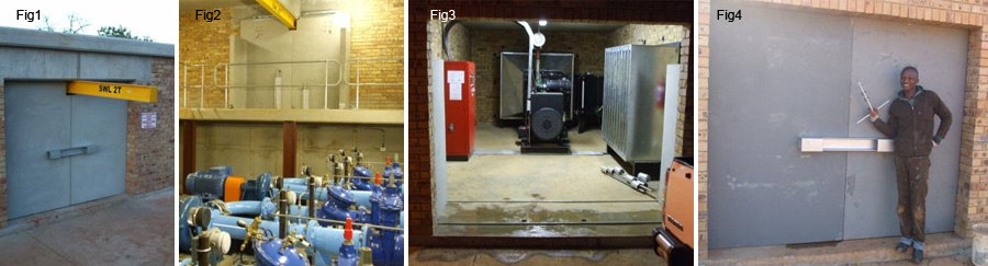
Pump stations that convey water to municipal areas cannot afford to go offline for more than a few hours. It is therefore essential that equipment such as electrical control panels/cables, motors, pumps, valves, brass fittings (see fig 2) as well as standby generators (see fig 3) are protected. Pump stations should therefore ideally be designed with (a) reinforced concrete roofs (b) 350mm cavity brick walls with the core made of mesh reinforced concrete or alternatively with 150/200mm RC walls), (c) no windows, but rather 100mm diameter ventilation holes, and (d) 60MPa reinforced concrete doors (see fig 1). (Concrete doors are immune to oxy-acetylene attack, and are too thick for angle grinders to penetrate, and with 5% (vol/vol) steel reinforcing are all but impenetrable to chisel attack).
Concrete doors typically vary in weight from 700kg through 2000kg depending on size. In this respect they are very dangerous should they fall over. A concrete door consisting of a single panel on hinges would run the risk of overturning – if for example the hinges fail; or if the fastening bolts fail or pull out of the wall; or if the wall fails owing to the weight of the door. Perhaps the most dangerous period occurs during the initial installation of the door – one mistake by the installation crew could have serious consequences.
Therefore concrete doors should have a three dimensional aspect to their design, so that they are substantially stable against overturning, both during the installation phase and the operational period. This may be achieved by adding a ‘stabilizing panel’ to the back of the main panel (see fig 8). Such doors may appropriately be called ‘L doors’, and for large doorways two L doors may be used to limit individual weights. Secondly, these doors should not be attached to the walls, but rather roll on tracks in the floor (see figs 3, 8, 9). Thus any weakness in the wall/bricks/mortar does not impact on the safety /stability of the door.
Opening sequence: Fig 4 shows the fully locked L doors. The first locking device (optional) is a ‘locking channel’ that is attached to a pair of screw-in lugs, one in each door (see bottom inset). The channel has two slots at the back to receive the lugs. Thereafter padlocks are attached to the lugs (see top inset). To open the door the padlocks are removed, the channel is pulled free from the lugs, and finally, the lugs themselves are screwed out of the door.
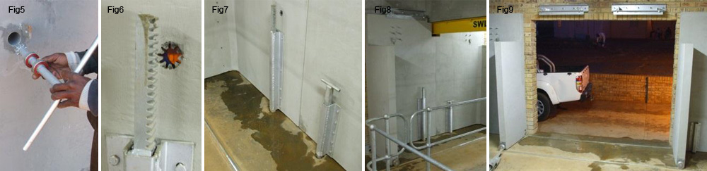
With the channel removed an access hole comes into view – see fig 5. An opening tool, which has a pinion at its front end, is inserted into the ‘access -tube’. The pinion passes through a matching ‘spline-disc’ attached to the far end of the access tube , and then on to engage a ‘rack-bar’ – see fig 6. In effect the pinion is the ‘key’ while the ‘spline-plate’ is the ‘key-hole’. The rack-bar runs in a guide-tube (see fig 7) which is fastened to the back of the door. When the door is in the closed position, the guide tube will be directly above an ‘anchor-hole’ in the floor, and the rack-bar will be inside this hole.
By turning the handle of the opening tool, the rack-bar will slide upwards and exit the anchor-hole, rendering the door unlocked. The door may now be pushed open, conveniently holding on the tool’s handle as a pushing point. Once the door is approximately 500mm open person access has been achieved. If however a large piece of equipment must be replaced, the opening -tool should be removed, and both doors pushed all the way open.
Note that a variety of other door designs are also available, depending on the application – see www.damsforafrica.com. Further products in our range include various concrete lids (for valve chambers), and various vaults with slidable/liftable members (for protection of transformers, borehole installations, stand alone control panels, etc). Products can be made to any size, all from 60MPa with up to 5% reinforcing.
Manufactured & installed by Dams for Africa. Contact details [email protected]. mobile +2782 416 8958 , tel +2711 475 8381/2764
Pump stations that convey water to municipal areas cannot afford to go offline for more than a few hours. It is therefore essential that equipment such as electrical control panels/cables, motors, pumps, valves, brass fittings (see fig 2) as well as standby generators (see fig 3) are protected. Pump stations should therefore ideally be designed with (a) reinforced concrete roofs (b) 350mm cavity brick walls with the core made of mesh reinforced concrete or alternatively with 150/200mm RC walls), (c) no windows, but rather 100mm diameter ventilation holes, and (d) 60MPa reinforced concrete doors (see fig 1). (Concrete doors are immune to oxy-acetylene attack, and are too thick for angle grinders to penetrate, and with 5% (vol/vol) steel reinforcing are all but impenetrable to chisel attack).
Concrete doors typically vary in weight from 700kg through 2000kg depending on size. In this respect they are very dangerous should they fall over. A concrete door consisting of a single panel on hinges would run the risk of overturning – if for example the hinges fail; or if the fastening bolts fail or pull out of the wall; or if the wall fails owing to the weight of the door. Perhaps the most dangerous period occurs during the initial installation of the door – one mistake by the installation crew could have serious consequences.
Therefore concrete doors should have a three dimensional aspect to their design, so that they are substantially stable against overturning, both during the installation phase and the operational period. This may be achieved by adding a ‘stabilizing panel’ to the back of the main panel (see fig 8). Such doors may appropriately be called ‘L doors’, and for large doorways two L doors may be used to limit individual weights. Secondly, these doors should not be attached to the walls, but rather roll on tracks in the floor (see figs 3, 8, 9). Thus any weakness in the wall/bricks/mortar does not impact on the safety /stability of the door.
Opening sequence: Fig 4 shows the fully locked L doors. The first locking device (optional) is a ‘locking channel’ that is attached to a pair of screw-in lugs, one in each door (see bottom inset). The channel has two slots at the back to receive the lugs. Thereafter padlocks are attached to the lugs (see top inset). To open the door the padlocks are removed, the channel is pulled free from the lugs, and finally, the lugs themselves are screwed out of the door.
With the channel removed an access hole comes into view – see fig 5. An opening tool, which has a pinion at its front end, is inserted into the ‘access -tube’. The pinion passes through a matching ‘spline-disc’ attached to the far end of the access tube , and then on to engage a ‘rack-bar’ – see fig 6. In effect the pinion is the ‘key’ while the ‘spline-plate’ is the ‘key-hole’. The rack-bar runs in a guide-tube (see fig 7) which is fastened to the back of the door. When the door is in the closed position, the guide tube will be directly above an ‘anchor-hole’ in the floor, and the rack-bar will be inside this hole.
By turning the handle of the opening tool, the rack-bar will slide upwards and exit the anchor-hole, rendering the door unlocked. The door may now be pushed open, conveniently holding on the tool’s handle as a pushing point. Once the door is approximately 500mm open person access has been achieved. If however a large piece of equipment must be replaced, the opening -tool should be removed, and both doors pushed all the way open.
Note that a variety of other door designs are also available, depending on the application – see www.damsforafrica.com. Further products in our range include various concrete lids (for valve chambers), and various vaults with slidable/liftable members (for protection of transformers, borehole installations, stand alone control panels, etc). Products can be made to any size, all from 60MPa with up to 5% reinforcing.